 With firmware version 4.50, my Garmin Nuvi no longer charges or uses power from a generic usb cable, which means the unit can only use a proprietary Garmin charger. When plugged into a generic cable, an error message appears: "The attached power cable cannot charge your device...".
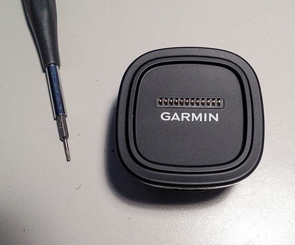
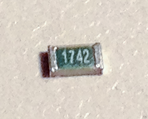
Fortunately, there is a simple way to fix this irritating problem and it requires only one tiny resistor. The proprietary Garmin cables contain a resistor connected between pins four and five of the mini usb connector, which signals to the device that the cable is authentic. The value of this resistor is 17.3kΩ, and instead of buying a new cable, the resistor can simply be soldered between pins four and five of the female usb connector inside of the cradle. The unit I have is model number 3597LMTHD, but this hack will also work for any other Nuvi unit.
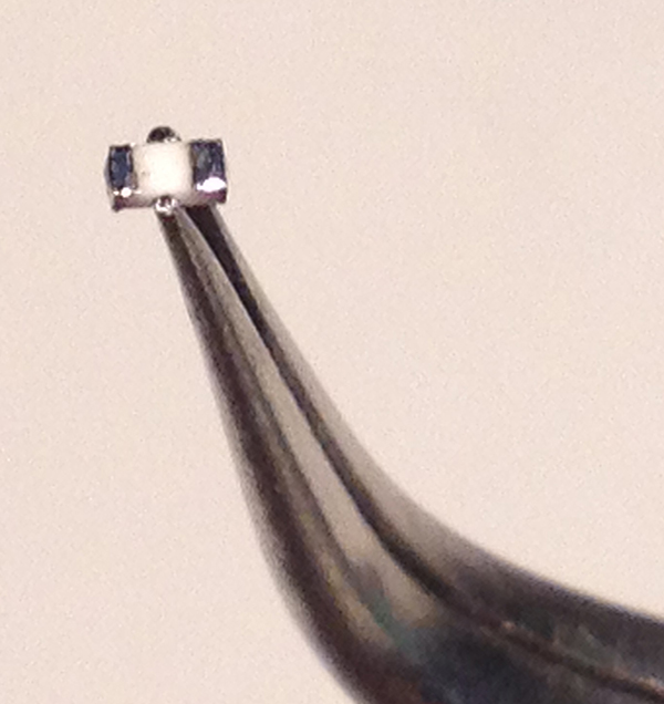
The specification calls for a 17.3kΩ resistor, but when I was ordering I could only find a 17.4kΩ resistor, and it works just fine. I chose to use a surface mount resistor in a 0603 package since it was the largest component which would fit between the pins of the connector. A 0402 package would probably fit perfectly, but I prefer to solder tiny grains of rice rather than tiny grains of sand. The resistor I used cost $0.40 when I ordered it from Mouser.
I would not recommend plugging a usb data cable between your computer and the modified usb jack. This is only for power, and will probably damage the usb bus of a computer if connected.
Pinout of Garmin Mini-USB-B Charger Cables
| Pin | Pin Name | Description |
| 1 | +5V | +5 Volts DC |
| 2 | Data | Computer i/o |
| 3 | Data | Computer i/o |
| 4 | Extra | 17.3kΩ -> GND |
| 5 | GND | Ground |
How–To Guide
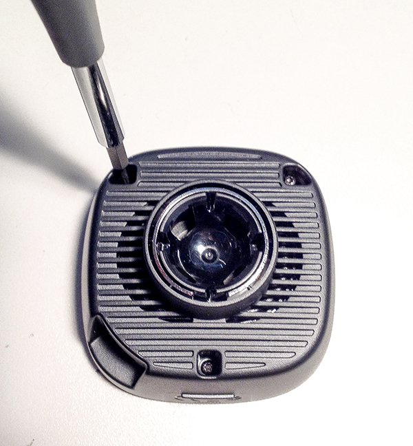
Disassemble the cradle using a Torx T-5 driver.
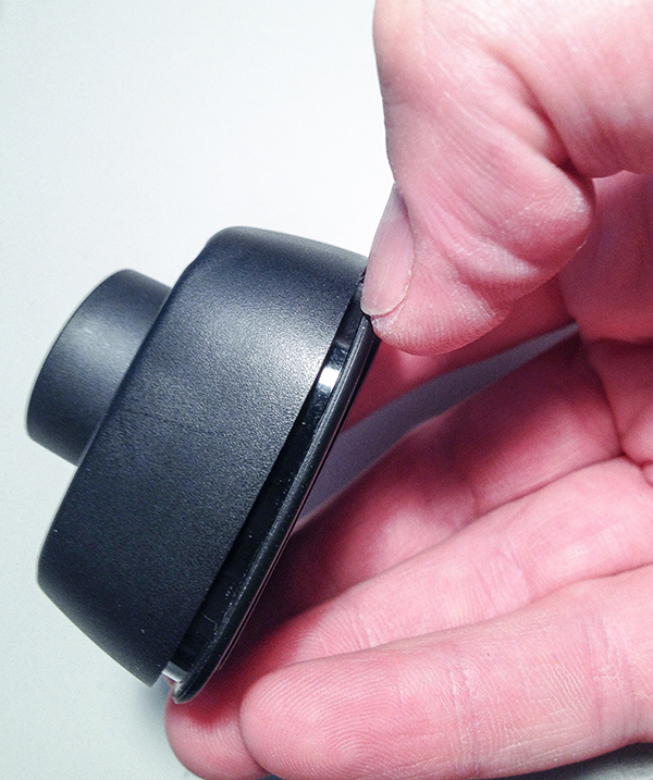
Use your thumbnail or a plastic blade to disengage the small inner latches and pry apart the cradle.
Remove the circuit board using the torx driver.
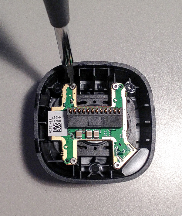
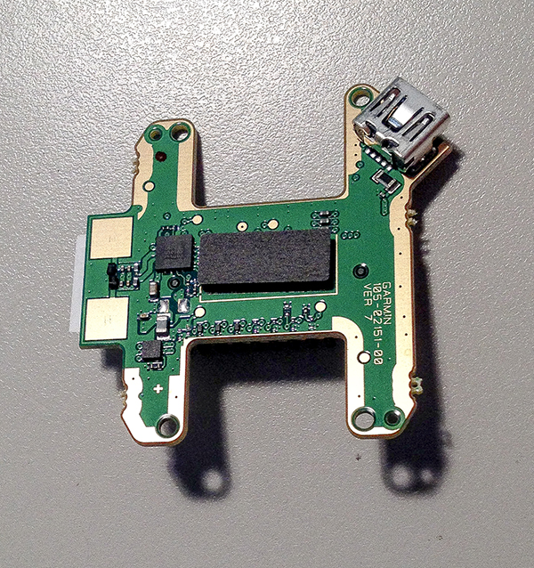
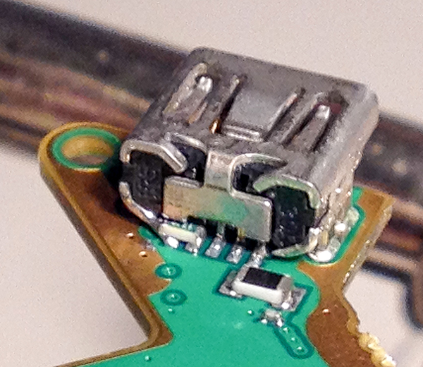
Apply some extra solder to pins five and four of the USB connector. These are the two leftmost pins.
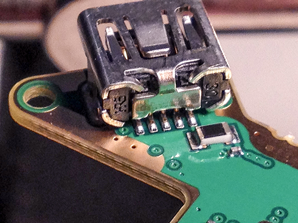
Apply a small amount of solder to the resistor's bottom pads.
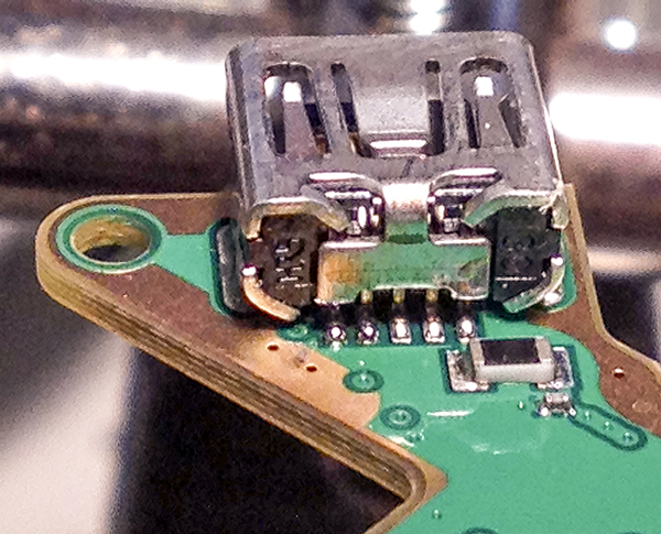
Align the right side of the resistor on top of the fourth pin and reflow the solder together, then reflow the left side of the resistor onto the fifth pin. It is fine if the left side touches the housing since pin five and the housing are grounded together.
Reassemble the cradle and the job is done.
Hi-Res Photos


